Power: Difference between revisions
m →Simple Double-Loop (TEG): Added warning to previous entry on TEG guide that no longer works as described. |
|||
| (25 intermediate revisions by 11 users not shown) | |||
| Line 1: | Line 1: | ||
The [[Station Engineer|Station Engineers]]' primary task is to generate electric power, which is essential for keeping a well-functioning space station from descending into darkness. Most computers, machines, and lighting fixtures require power to operate, among others. | |||
= Supply and Demand = | |||
[[File:Power Monitoring Console.png|thumb|Use the Power Monitoring Console to determine the station's power demand]] | |||
Running an efficient power operation is about delicately balancing the supply of power from generators with demand from station equipment. Thanks to cutting-edge energy storage technology (SMES, and batteries in substations and APCs) aboard NanoTransen stations, generators do not have to always match instantaneous station demand; it is enough to generate enough power to meet the average station demand. | Running an efficient power operation is about delicately balancing the supply of power from generators with demand from station equipment. Thanks to cutting-edge energy storage technology (SMES, and batteries in substations and APCs) aboard NanoTransen stations, generators do not have to always match instantaneous station demand; it is enough to generate enough power to meet the average station demand. | ||
Use the Power Monitoring Console to determine the station's power demand. In a well-functioning station, SMES balance the instantaneous demand with supply. Don't let them run out! | Use the Power Monitoring Console to determine the station's power demand. In a well-functioning station, SMES balance the instantaneous demand with supply. Don't let them run out! | ||
| Line 15: | Line 12: | ||
It is better to be in a long-term energy surplus than an energy deficit. On the other hand, if your station is powered by non-renewable sources like the Anti-Matter Engine (AME), generating much more power than you need wastes fuel and contributes to space warming, not to mention, wastes cargo's money <s>which they would have wasted on a lasers crate anyway</s>. | It is better to be in a long-term energy surplus than an energy deficit. On the other hand, if your station is powered by non-renewable sources like the Anti-Matter Engine (AME), generating much more power than you need wastes fuel and contributes to space warming, not to mention, wastes cargo's money <s>which they would have wasted on a lasers crate anyway</s>. | ||
{{Clear|both}} | |||
Power | = The Power Hierarchy = | ||
[[File:Minimal power example.png|thumb|Example of a station power network. The generator feeds a SMES through a cable terminal, which in turn supplies a substation, which in turn supplies an APC, which powers critical station equipment]] | |||
[[File: | [[File:SS14 PowerHD.png|thumb|right|A screenshot showing an example of a power network. Solar panels produce HV power, which is then buffered with a SMES and redistributed.]] | ||
Power transmission in SS14 comes in three different flavors, high voltage (HV) cables (orange), medium voltage (MV) cables (yellow) and low voltage (LV) cables (green). | |||
Power flows from generators and power storage via HV cables to substations around the station. From substations, MV cables going out transmit power from the substation and connected grid to area power controllers (APCs) where LV cables take the power the rest of the way to consumers (3-4 tile radius from the APC to devices in the area). '''A cable must be placed under generators, storage, substations and APCs for them to function'''. | Power flows from generators and power storage via HV cables to substations around the station. From substations, MV cables going out transmit power from the substation and connected grid to area power controllers (APCs) where LV cables take the power the rest of the way to consumers (3-4 tile radius from the APC to devices in the area). '''A cable must be placed under generators, storage, substations and APCs for them to function'''. | ||
=== Separating your Grid === | === Separating your Grid === | ||
One device not mentioned so far is the cable terminal. In order to separate part of your power network you will need to use a cable terminal, with a HV cable on the terminal box side and the wire side facing towards a SMES. Note the cable terminal will act as a separator for HV cable, if two HV cables are right | One device not mentioned so far is the cable terminal. In order to separate part of your power network you will need to use a cable terminal, with a HV cable on the terminal box side and the wire side facing towards a SMES. Note the cable terminal will act as a separator for HV cable, if two HV cables are right next to each other and a connecter is placed upon them it will separate those two cables. When a HV cable is then placed under the SMES this creates two distinct HV cable networks; the side with your generation on which ends at the cable terminal, and the storage / supply side which starts at the SMES and goes out to substations. | ||
Currently if you place a substation on the generation side of your SMES it will drain into said SMES as a supplier. This is important as in this scenario if there isn't enough generation, the substation will drain to empty causing a blackout in its connected APCs while everything on the SMES side will remain powered. | Currently if you place a substation on the generation side of your SMES it will drain into said SMES as a supplier. This is important as in this scenario if there isn't enough generation, the substation will drain to empty causing a blackout in its connected APCs while everything on the SMES side will remain powered. | ||
== Generation == | {{clear}} | ||
= Power Generation Methods = | |||
== Temporary Power Generation == | |||
=== Small Portable Generators === | |||
The simplest and most basic of all generators on this list are the "P.A.C.M.A.N." line of portable generators. The J.R.P.A.C.M.A.N. can be found in maintenance areas, and runs on simple welding fuel, also found in maintenance. Anchor it to an {{item icon|LV|l=LV cable}} and power it up. Because it generates LV power, it is only able to power one APC's worth of devices. It also generates exhaust fumes, so make sure you set it up in a well-ventilated area. | |||
The other "P.A.C.M.A.N." generators are intended for usage by engineering for advanced power scenarios. Bootstrapping the engine, powering departments, and so on. unlike the J.R.P.A.C.M.A.N., They connect directly to {{item icon|MV|l=MV}} or {{item icon|HV|l=HV}} power cables, and are able to switch between them for flexibility. the standard P.A.C.M.A.N. is powered by solid plasma, and the S.U.P.E.R.P.A.C.M.A.N. runs on uranium, and produces enough power for things like shuttles. | |||
=== The Antimatter Engine === | === The Antimatter Engine === | ||
| Line 218: | Line 224: | ||
The display of the AME controller indicates if the AME has suffered internal damage. If it is blue, at least 50% of the internal shielding is remaining. If the display shows a red wave, it is below 50%. If the display starts showing swear words, the AME is about to explode. | The display of the AME controller indicates if the AME has suffered internal damage. If it is blue, at least 50% of the internal shielding is remaining. If the display shows a red wave, it is below 50%. If the display starts showing swear words, the AME is about to explode. | ||
== Basic Permanent Power == | |||
=== Solar Power === | === Solar Power === | ||
| Line 234: | Line 242: | ||
A solar tracker device is made using a solar assembly flatpack as well, so don't forget to count in an extra one. It's made by unpacking a solar assembly from a flatpack, putting a solar tracker electronics inside the solar assembly and then adding 2 pieces of glass. | A solar tracker device is made using a solar assembly flatpack as well, so don't forget to count in an extra one. It's made by unpacking a solar assembly from a flatpack, putting a solar tracker electronics inside the solar assembly and then adding 2 pieces of glass. | ||
=== | === The Thermoelectric Generator (TEG) === | ||
The | The TEG involves atmospherics, so you should have a decent understanding of [[Atmospheric_Technician|atmos]] before setting it up by yourself. As evidence of this point, there are several ways to set up the TEG. As this section is filled out, there may be several guides posted on different ways to configure the TEG. However, there is one key insight that you should keep in mind which establishes the law that defines how each system is designed. That is, '''the TEG is powered by a temperature exchange between hot and cold gasses.''' As such, one side should be very hot, and the other should be (relative to the other side) quite cold. Every configuration of TEG will result in this kind of configuration. | ||
==== Simple Double-Loop (TEG) ==== | |||
To create this TEG setup you don't need any active knowledge of what's going on. However, I ''highly'' recommend you have knowledge of what all of the pieces do so that you can test and make modifications of your own. | |||
{{Callout|Warning|h=<big>Out of date!</big>|Currently the information that was given here is out of date 6/9/25 due to change log affecting thermal efficiency. Please wait for someone to update the information.|align=Center}} | |||
===== Pre-amble ===== | |||
The most important lesson is why we would use one pump over another. | |||
# Gas pumps will continue to operate '''''until''''' 4500 kPa is reached within the output pipe network '''''regardless of the volume'''''. | |||
# Volumetric gas pumps will continue to operate '''''until''''' 200 Liters is reached in '''''all''''' of the pipes within the output pipe network '''''regardless of pressure'''''. | |||
If you were to pump both a gas pump and a volumetric gas pump into an empty network they would transfer at equivalent speeds of 1 L/s to 45 kPa. (This is just based off of testing and is as accurate as my eyes could perceive, so it's likely not mathematically accurate. It's close enough to be accurate in the vast majority of applications from what I've found.) | |||
This difference is highly important when considering what pump to use. For example, in high heat networks '''''volumetric gas pumps are preferred''''' because they do not care about the pressure created by the heat and only care about the volume within the network. Volumetric pipes are also good at providing a means of storage because they will fill a network based on volume rather than pressure. We can use this to our advantage in a multitude of places including replacing gas miner pumps to be volumetric so that they do not idle. | |||
[[File:Pump_differences.png|alt=Pump differences|center]] | |||
===== Pre-mix ===== | |||
The premix is important to sustaining a long term TEG. Canisters are nice in ease of use but will rapidly drain and require you to pay attention to when it needs a refill. | |||
The | # The mix we will be using for this setup is '''96% oxygen''' and '''4% plasma'''. (Note, anything above 3% plasma will hit supersaturation as per comments on line 41)<ref>https://github.com/space-wizards/space-station-14/blob/master/Content.Server/Atmos/Reactions/PlasmaFireReaction.cs#L47</ref> | ||
# The Primary port refers to the straight line created by arrows. (AKA where the plasma is coming from). The side port refers to the arrow coming from side. (AKA where the oxygen is coming from). | |||
[[File:TEG_pre-mix.png|alt=TEG pre-mix|center|1034x1034px]] | |||
=== | ===== The Burn-Chamber ===== | ||
This is a controversial one. My reasoning for choosing a handmade burn chamber over the pre-mapped ones is that the pre-mapped burn chambers tend to be in awkward spots, easy to sabotage, takes longer to setup. I find that TEG is not only about power output but how ''fast'' you can deliver that power output. If setting up TEG takes an extra 5-10 minutes compared to making your own burn chamber, then in my opinion, it is not worth the effort. Additionally due to recent patches reinforced glass can be directly upgraded by just clicking on it with Plasteel in hand. Plasma glass also got a 16x strength nerf, making it the same strength as normal glass. This makes the shuttle glass setup to be significantly more resistant to breaking. | |||
# Make sure that you turn on the volumetric pump and set it to 20 L/s before proceeding. It's also important to turn off the air injector and close the valve to prevent any accidental leaks of plasma mix into the ambient room. | |||
[[File:Burn_chamber_part_1.png|alt=Burn chamber part 1|center]] | |||
# Add the reinforced glass with the RCD '''''after''''' you have turned on the volumetric gas pump. | |||
[[File:Burn_Chamber_part_2.png|alt=Burn Chamber part 2|center]] | |||
The | ===== Starting the Hot-Loop ===== | ||
The hot loop is one-half of the setup and providing it with sufficiently hot temperatures and thus pressure is key to producing a high amount of steady energy. | |||
# Real simple loop. One volumetric gas pump before the TEG aids in providing movement to the gas within the network. Technically the TEG does not care what direction the gas is flowing. '''''However''''', it is critical to keep in mind that if you pump gas on the hop loop in one direction, you '''''must''''' pump the cold loop in the '''''opposite''''' direction. If you do not provide opposite flows between the loops the TEG will not function properly. | |||
[[File:Hot_loop_part_1.png|alt=Hot loop part 1|center]] | |||
A | # A secondary key importance to the hot loop is leaking volume from the loop. This is important because it prevents '''''volumetric''''' lockout so it aids in keeping the hot gas flowing in a loop which is what we want. | ||
[[File:Hot_loop_part_2.png|alt=hot loop part 2|center|668x668px]] | |||
=== | ===== The Cold-Loop ===== | ||
The cold loop is really simple to setup. The logic behind the cold loop is a bit more complicated though. Essentially we want it to be as cold as possible '''''without losing pressure''''' as pressure plays a vital role in energy production. This is why I have found that using a single spaced radiator is both the most time efficient and does not compromise the pressure. It may scare some more experienced atmosians to try this out but I encourage you to try it. Through extensive testing I have found that the cold loop prefers to be between 100C to 400C which typically ends up being ~4k kPa. | |||
# The build is simple here but the most important factor is to use a '''''plasma canister''''' over any other. This is because plasma is more thermo-conductive than other gasses. This leads to usually a gain in 20kw of power '''just for using plasma canister over other canisters.''' | |||
[[File:Cold_loop_part_1.png|alt=Cold loop part 1|center]] | |||
# Now we make a horseshoe shape around the radiator with directional reinforced windows using your RCD. Put a gas trap by placing a holo-projected firelock with your holographic projector. [[File:Cold_loop_part_2.png|alt=Cold loop part 2|center]] | |||
# Space the floor tile below the radiator and then close the box of directional reinforced windows. (Both using your RCD) [[File:Cold_loop_part_3.png|alt=Cold loop part 3|center]] | |||
==== | ===== Finishing the Hot-Loop ===== | ||
It's time to finish the hot loop now that we have everything else setup. | |||
# Place a holographic firelock on the empty space of the "rectangle" burn chamber we created earlier. Then light a flare or a welder and place it on top of the passive vent. '''Make sure to turn on the air injector and valve at this point. To do so click on them to make them to have a green indicator on their "light".''' | |||
[[File:Hot_loop_part_3.png|alt=Hot loop part 3|center|571x571px]] | |||
# Make sure that the air injector and the valve are on and the fire is starting to burn. Close the box with another reinforced window where the holographic airlock is. | |||
[[File:Hot_loop_part_4.png|alt=Hot loop part 4|center]] | |||
# Use a gas analyzer on the pipe that's coming out of the output of the burn chamber. Wait until it is ~20,000C. Turn on the gas pump at 1500 kPa. This pump controls your power output maximum. [[File:Hot_loop_part_5.png|alt=Hot loop part 5|center|920x920px]] | |||
# 1500kPa on the gas pump produces at a maximum ~420kW of power. [[File:TEG_power_output_.png|alt=TEG power output|center]] | |||
===== Final thought / Full build ===== | |||
This build is capable of a maximum output of 1.4 MW of power at 4500 kPa of pressure on the gas pump. | |||
[[File:Teg_full_power_output.png|alt=Teg full power output|center]] | |||
This is the completed TEG image for quick reference. | |||
[[File:Full_TEG_build.png|alt=Full TEG build|center]] | |||
===== FAQ ===== | |||
# '''I followed all the steps but my TEG doesn't produce nearly as much power, why's that?''' | |||
## What's most likely occurring is that you have multiple power sources on the station active at one time. The way that power is displayed is that it shows its active contribution to the station and '''not''' it's theoretical maximum. If you were to turn off all power sources on the station '''and''' add more power intensive devices then the TEG would show a higher value. This is also why I have a substation and an emitter below the TEG. I altered the power draw of the emitter to be enormous so that the TEG can show how much power it should be producing at max draw. Power distribution and how it takes priority is a whole another topic to delve into but if you're seeing numbers ranging from 100-200kw then you've built it correctly. You could even turn down the gas pump to accommodate for other power sources. Play with the pressure and get a feel for what it's capable of. | |||
# '''I messed up the gas chamber really bad how do I fix it?''' | |||
## Don't worry it's an easy fix with this setup. | |||
## Just turn off the valve inputting into the burn chamber and max out the output of the gas pump coming out of the burn chamber. ## You should also max out the volumetric gas pump coming out of the hot loop that's going into space. | |||
## Check if the burn chamber is empty (use a gas analyzer on the output pipe). | |||
## When the burn chamber is empty fix the problem that broke the burn chamber, turn off the gas pump that's coming out of the output of the burn chamber, and then ignite a new flare/welder on top of the passive vent again. | |||
## Close the burn chamber and then turn on the valve on the input side of the burn chamber, wait for 20,000C and turn on the output gas pump. | |||
## This should empty your burn chamber without any major fixes. | |||
=== Radioisotope Thermoelectric Generators (RTGs) === | |||
[[File:RTG.png|RTG|128px]] | |||
[[File:Damaged_RTG.png|Damaged RTG|128px]] | |||
Making power using an RTG is similar to making power using solar. RTGs only provide 10 kW<ref>https://github.com/space-wizards/space-station-14/blob/6e91190478ec03e038ff1c3a10ecd632808f281e/Resources/Prototypes/Entities/Structures/Power/Generation/generators.yml#L239</ref> of power, but they provide it for free and for the entire round. Basically, if you connect an RTG to your power grid, it'll give you free power. Sometimes, RTGs are damaged. Damaged RTGs<ref>https://github.com/space-wizards/space-station-14/blob/6e91190478ec03e038ff1c3a10ecd632808f281e/Resources/Prototypes/Entities/Structures/Power/Generation/generators.yml#L275-L318</ref> behave just like regular ones, but they're radioactive. | |||
==== | ==== Radioactive Radioisotope Thermoelectric Generator (RRTG) Setup ==== | ||
You can use the radioactive nature of the RTG to your advantage. Lord Singuloth generates power by emitting radiation into radiation collectors. Likewise, you can surround an RRTG in radiation collectors and generate as much as ~200-300KW with one RRTG. | |||
== Containment-based Engines == | |||
- | === Gravitational Singularity Engine === | ||
The Gravitational Singularity Engine is one of the most well known and potentially dangerous ways of generating power in Space Station 14. To build it, you need a [https://github.com/space-wizards/space-station-14/tree/6e91190478ec03e038ff1c3a10ecd632808f281e/Resources/Prototypes/Entities/Structures/Power/Generation/PA particle accelerator] and [https://github.com/space-wizards/space-station-14/blob/6e91190478ec03e038ff1c3a10ecd632808f281e/Resources/Prototypes/Entities/Structures/Power/Generation/Singularity/generator.yml singulator generator] to spawn a singularity, [https://github.com/space-wizards/space-station-14/blob/6e91190478ec03e038ff1c3a10ecd632808f281e/Resources/Prototypes/Entities/Structures/Power/Generation/Singularity/containment.yml#L1-L68 containment field generators] to trap it in a tiny box so it doesn't kill everyone, [https://github.com/space-wizards/space-station-14/blob/6e91190478ec03e038ff1c3a10ecd632808f281e/Resources/Prototypes/Entities/Structures/Power/Generation/Singularity/emitter.yml#L1-L101 emitters] to power the containment field generators, and [https://github.com/space-wizards/space-station-14/blob/6e91190478ec03e038ff1c3a10ecd632808f281e/Resources/Prototypes/Entities/Structures/Power/Generation/Singularity/collector.yml#L1-L108 radiation collectors] to turn the radiation the singularity generates into sweet, sweet power. | |||
If someone turns off the containment field, the singularity will escape and everyone will die. If someone turns the particle accelerator up too much for too long, the singularity will get too big, escape, and then everyone will die. If you get hit by emitter beams, they'll hurt you real bad, and you might die. The singularity engine is super deadly - but damn if it doesn't give the station lots of power. | |||
To keep the singularity from breaking containment, set the particle accelerator to 1. At this setting it will eventually die out. Any more than that and it'll slowly (or quickly) grow until it escapes. Turning it up to higher numbers is OK for short bursts just to kickstart the engine, though - but be careful. | |||
The largest size singularity before you risk it breaking loose can generate between 1.4 and 1.6 MW with 24 radiation collectors. The amount of power the singularity engine generates changes from station to station, because the layout of the engine is different on different stations. One source of the variance is the location of the radiation collectors on each station. Radiation falls off over distance, so on stations where the radiation collectors are further away, you'll get less power. | |||
Radiation collectors require plasma gas to run. If your singularity isn't giving you any power, make sure that your radiation collectors are on and contain tanks full of plasma. | |||
= | A tell-tale sign of the singularity's proximity is the [https://www.youtube.com/watch?v=V5T92L4JHcg gravitational lensing effect]; the closer you are, the stronger the distortion. | ||
[ | ===[https://www.youtube.com/watch?v=KdleuMdtQnM ALL HAIL LORD SINGULOTH]=== | ||
As stated before, the singularity is an incredible powerful resource, equally deadly and beautiful, and in the <strike>wrong</strike> right hands, an unpredictable tool of chaos: a traitor seeking to force an evacuation, or die a glorious death may find it useful to leave the particle accelerator on the 2 setting or higher in order to swell the singularity past containment. As one might expect, it is typically a good idea to make sure you clear a wide distance from the | |||
'''DISCLAIMER: It is generally inadvisable to intentionally loose the singularity as a non-antag without good reason. Be prepared to get robusted, lynched and/or banned if you set it loose for shits and giggles.''' | |||
[[Category:Guides]] | [[Category:Guides]] | ||
Latest revision as of 19:46, 14 June 2025
The Station Engineers' primary task is to generate electric power, which is essential for keeping a well-functioning space station from descending into darkness. Most computers, machines, and lighting fixtures require power to operate, among others.
Supply and Demand
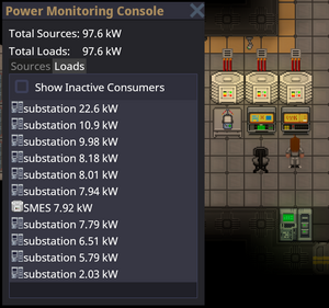
Running an efficient power operation is about delicately balancing the supply of power from generators with demand from station equipment. Thanks to cutting-edge energy storage technology (SMES, and batteries in substations and APCs) aboard NanoTransen stations, generators do not have to always match instantaneous station demand; it is enough to generate enough power to meet the average station demand.
Use the Power Monitoring Console to determine the station's power demand. In a well-functioning station, SMES balance the instantaneous demand with supply. Don't let them run out!
If long term demand exceeds supply, you will have angry station inhabitants complaining about lack of power. When supply exceeds demand, the extra power is used to charge energy storage devices. When all energy storage devices are full, the excess power is safely dissipated into space.
It is better to be in a long-term energy surplus than an energy deficit. On the other hand, if your station is powered by non-renewable sources like the Anti-Matter Engine (AME), generating much more power than you need wastes fuel and contributes to space warming, not to mention, wastes cargo's money which they would have wasted on a lasers crate anyway.
The Power Hierarchy
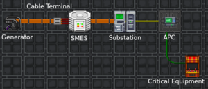
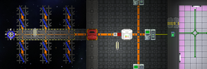
Power transmission in SS14 comes in three different flavors, high voltage (HV) cables (orange), medium voltage (MV) cables (yellow) and low voltage (LV) cables (green).
Power flows from generators and power storage via HV cables to substations around the station. From substations, MV cables going out transmit power from the substation and connected grid to area power controllers (APCs) where LV cables take the power the rest of the way to consumers (3-4 tile radius from the APC to devices in the area). A cable must be placed under generators, storage, substations and APCs for them to function.
Separating your Grid
One device not mentioned so far is the cable terminal. In order to separate part of your power network you will need to use a cable terminal, with a HV cable on the terminal box side and the wire side facing towards a SMES. Note the cable terminal will act as a separator for HV cable, if two HV cables are right next to each other and a connecter is placed upon them it will separate those two cables. When a HV cable is then placed under the SMES this creates two distinct HV cable networks; the side with your generation on which ends at the cable terminal, and the storage / supply side which starts at the SMES and goes out to substations.
Currently if you place a substation on the generation side of your SMES it will drain into said SMES as a supplier. This is important as in this scenario if there isn't enough generation, the substation will drain to empty causing a blackout in its connected APCs while everything on the SMES side will remain powered.
Power Generation Methods
Temporary Power Generation
Small Portable Generators
The simplest and most basic of all generators on this list are the "P.A.C.M.A.N." line of portable generators. The J.R.P.A.C.M.A.N. can be found in maintenance areas, and runs on simple welding fuel, also found in maintenance. Anchor it to an ![]() LV cable and power it up. Because it generates LV power, it is only able to power one APC's worth of devices. It also generates exhaust fumes, so make sure you set it up in a well-ventilated area.
LV cable and power it up. Because it generates LV power, it is only able to power one APC's worth of devices. It also generates exhaust fumes, so make sure you set it up in a well-ventilated area.
The other "P.A.C.M.A.N." generators are intended for usage by engineering for advanced power scenarios. Bootstrapping the engine, powering departments, and so on. unlike the J.R.P.A.C.M.A.N., They connect directly to ![]() MV or
MV or ![]() HV power cables, and are able to switch between them for flexibility. the standard P.A.C.M.A.N. is powered by solid plasma, and the S.U.P.E.R.P.A.C.M.A.N. runs on uranium, and produces enough power for things like shuttles.
HV power cables, and are able to switch between them for flexibility. the standard P.A.C.M.A.N. is powered by solid plasma, and the S.U.P.E.R.P.A.C.M.A.N. runs on uranium, and produces enough power for things like shuttles.
The Antimatter Engine
The Antimatter Engine (AME) is not always the main source of power for most stations. However, the AME should be your temporary fix in order to keep the station powered until you can get one or more engines up (TEG, Tesla, Singularity, Solars). Engineering is responsible for setting up the AME at round start.
Setup
- Grab AME parts from a Packaged antimatter reactor crate and place one on each floor tile you want a piece of the reactor. The minimum is a 3×3 square, which gives one core.
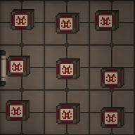
3×3, 1-core AME - With a multitool in hand, click the AME parts on the floor to build a piece of the reactor. If you mess up, you can deconstruct a built reactor with a lit welder.
- Open the antimatter control unit crate to obtain an AME Controller. Place it next to the reactor you just built and wrench it down. The HV cable underneath the controller will carry power produced from the AME. Make sure the controller is on HV wire.
- Open the antimatter containment jar crate to obtain antimatter containment jars. This is the fuel for the AME. With it in hand, click on the controller to place it in the AME. Change the Injection Amount to the desired level (see table below) and click Toggle Injection to turn the AME on.
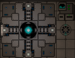
Finished AME

|
Warning
Do not set injection greater than (2× the number of cores). Doing so will cause reactor instability, which will sooner or later destroy the reactor. |
The wattage produced by the AME in different configurations is shown below. The color indicates the state - green: safe, yellow: Overloaded (explodes eventually), Orange: Heavily Overloaded (explodes soon), Red: Extremely Overloaded (explodes within the minute)
| Cores | |||||||||||
|---|---|---|---|---|---|---|---|---|---|---|---|
| 1 | 2 | 3 | 4 | 5 | 6 | 7 | 8 | 9 | 10 | ||
| Injection | 2 | 80.0 | 40.0 | 26.7 | 20.0 | 16.0 | 13.3 | 11.4 | 10.0 | 8.9 | 8.0 |
| 4 | 320.0 | 160.0 | 106.7 | 80.0 | 64.0 | 53.3 | 45.7 | 40.0 | 35.6 | 32.0 | |
| 6 | 720.0 | 360.0 | 240.0 | 180.0 | 144.0 | 120.0 | 102.9 | 90.0 | 80.0 | 72.0 | |
| 8 | 1,280.0 | 640.0 | 426.7 | 320.0 | 256.0 | 213.3 | 182.9 | 160.0 | 142.2 | 128.0 | |
| 10 | 2,000.0 | 1,000.0 | 666.7 | 500.0 | 400.0 | 333.3 | 285.7 | 250.0 | 222.2 | 200.0 | |
| 12 | 2,880.0 | 1,440.0 | 960.0 | 720.0 | 576.0 | 480.0 | 411.4 | 360.0 | 320.0 | 288.0 | |
| 14 | 3,920.0 | 1,960.0 | 1,306.7 | 980.0 | 784.0 | 653.3 | 560.0 | 490.0 | 435.6 | 392.0 | |
| 16 | 5,120.0 | 2,560.0 | 1,706.7 | 1,280.0 | 1,024.0 | 853.3 | 731.4 | 640.0 | 568.9 | 512.0 | |
| 18 | 6,480.0 | 3,240.0 | 2,160.0 | 1,620.0 | 1,296.0 | 1,080.0 | 925.7 | 810.0 | 720.0 | 648.0 | |
| 20 | 8,000.0 | 4,000.0 | 2,666.7 | 2,000.0 | 1,600.0 | 1,333.3 | 1,142.9 | 1,000.0 | 888.9 | 800.0 | |
| 22 | 9,680.0 | 4,840.0 | 3,226.7 | 2,420.0 | 1,936.0 | 1,613.3 | 1,382.9 | 1,210.0 | 1,075.6 | 968.0 | |
Maintenance
The AME will stop generating power when its fuel has been used up. It is wise to periodically check on the AME to make sure it is not out of fuel. If the fuel runs out, you must refuel it:
- Make sure injection is off.
- Eject the existing fuel jar from the AME.
- Place a new fuel jar into the AME.
- Turn the AME back on.
It is also wise to periodically check on the AME, since it is a prime target for sabatoge.
You can see if the AME is currently overloaded (and thus taking damage), if the cores glow in a "+"-shape instead of a ball.
The display of the AME controller indicates if the AME has suffered internal damage. If it is blue, at least 50% of the internal shielding is remaining. If the display shows a red wave, it is below 50%. If the display starts showing swear words, the AME is about to explode.
Basic Permanent Power
Solar Power
Solar power is a passive means of generating power. A solar array is made up of a number of solar panels, a single solar tracker device and a solar control computer (console) nearby to properly control and manage the panels.
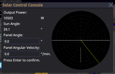
Most if not all solar arrays start off not connected to the station, and need to be connected via HV cables underneath each panel and connected back to the station. Once connected, use the solar control computer to change the angle and speed of tracking for the panels as shown below:
Notice the graph on the right has a T shaped white line and a yellow / golden line. The aim is to alter the panel angle (white T line) to match the sun angle (yellow line). Some experimentation might be needed to setup the angular velocity correctly so that the lines stay in sync and generate maximum wattage. Note: a general start for the angular velocity is somewhere around 5-6 degrees per minute.
A typical panel near max output will produce 1500W (1.5kW). This would be enough to power roughly 1 machine and 1 computer (this figure may change as balance changes are made).
Solar panels can be ordered through Cargo by crates. One crate will contain **six** solar assembly flatpacks. A flatpack is unpacked using a multitool, which produces an already mounted solar assembly. 2 pieces of glass then need to be added to complete the solar panel.
A solar tracker device is made using a solar assembly flatpack as well, so don't forget to count in an extra one. It's made by unpacking a solar assembly from a flatpack, putting a solar tracker electronics inside the solar assembly and then adding 2 pieces of glass.
The Thermoelectric Generator (TEG)
The TEG involves atmospherics, so you should have a decent understanding of atmos before setting it up by yourself. As evidence of this point, there are several ways to set up the TEG. As this section is filled out, there may be several guides posted on different ways to configure the TEG. However, there is one key insight that you should keep in mind which establishes the law that defines how each system is designed. That is, the TEG is powered by a temperature exchange between hot and cold gasses. As such, one side should be very hot, and the other should be (relative to the other side) quite cold. Every configuration of TEG will result in this kind of configuration.
Simple Double-Loop (TEG)
To create this TEG setup you don't need any active knowledge of what's going on. However, I highly recommend you have knowledge of what all of the pieces do so that you can test and make modifications of your own.
Pre-amble
The most important lesson is why we would use one pump over another.
- Gas pumps will continue to operate until 4500 kPa is reached within the output pipe network regardless of the volume.
- Volumetric gas pumps will continue to operate until 200 Liters is reached in all of the pipes within the output pipe network regardless of pressure.
If you were to pump both a gas pump and a volumetric gas pump into an empty network they would transfer at equivalent speeds of 1 L/s to 45 kPa. (This is just based off of testing and is as accurate as my eyes could perceive, so it's likely not mathematically accurate. It's close enough to be accurate in the vast majority of applications from what I've found.)
This difference is highly important when considering what pump to use. For example, in high heat networks volumetric gas pumps are preferred because they do not care about the pressure created by the heat and only care about the volume within the network. Volumetric pipes are also good at providing a means of storage because they will fill a network based on volume rather than pressure. We can use this to our advantage in a multitude of places including replacing gas miner pumps to be volumetric so that they do not idle.
Pre-mix
The premix is important to sustaining a long term TEG. Canisters are nice in ease of use but will rapidly drain and require you to pay attention to when it needs a refill.
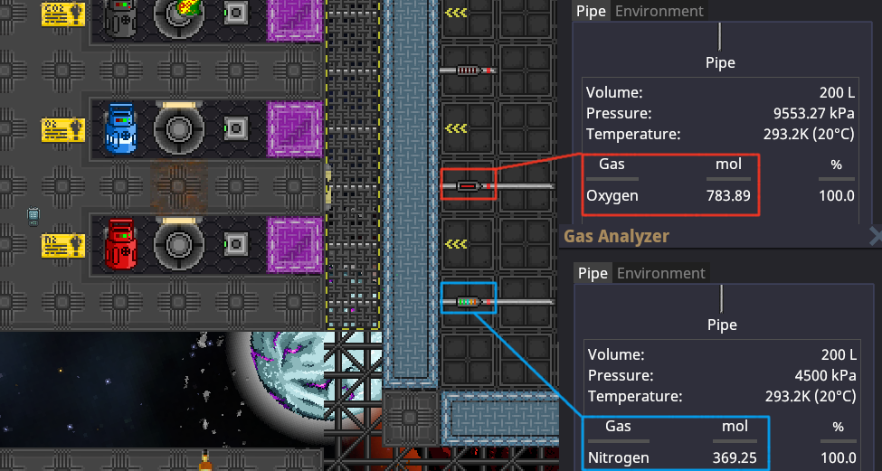
- The mix we will be using for this setup is 96% oxygen and 4% plasma. (Note, anything above 3% plasma will hit supersaturation as per comments on line 41)[1]
- The Primary port refers to the straight line created by arrows. (AKA where the plasma is coming from). The side port refers to the arrow coming from side. (AKA where the oxygen is coming from).
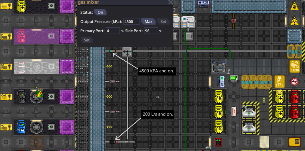
The Burn-Chamber
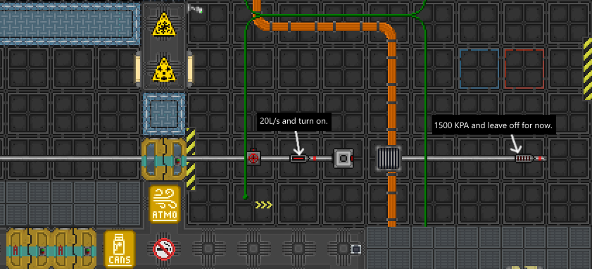
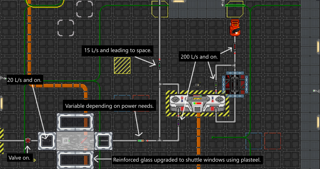
This is a controversial one. My reasoning for choosing a handmade burn chamber over the pre-mapped ones is that the pre-mapped burn chambers tend to be in awkward spots, easy to sabotage, takes longer to setup. I find that TEG is not only about power output but how fast you can deliver that power output. If setting up TEG takes an extra 5-10 minutes compared to making your own burn chamber, then in my opinion, it is not worth the effort. Additionally due to recent patches reinforced glass can be directly upgraded by just clicking on it with Plasteel in hand. Plasma glass also got a 16x strength nerf, making it the same strength as normal glass. This makes the shuttle glass setup to be significantly more resistant to breaking.
- Make sure that you turn on the volumetric pump and set it to 20 L/s before proceeding. It's also important to turn off the air injector and close the valve to prevent any accidental leaks of plasma mix into the ambient room.
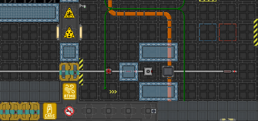
- Add the reinforced glass with the RCD after you have turned on the volumetric gas pump.
Starting the Hot-Loop
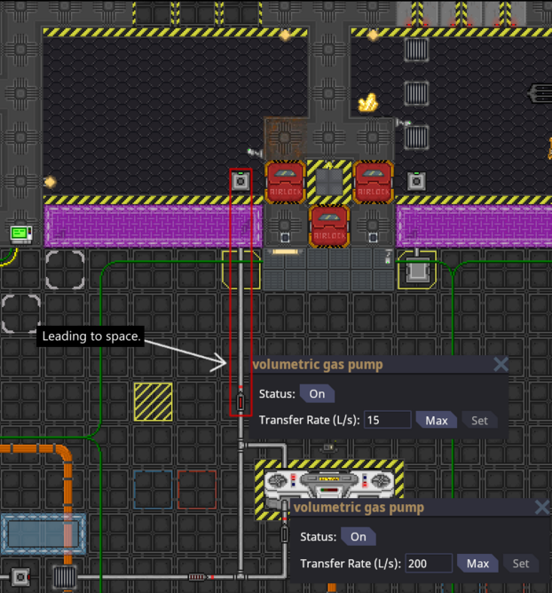
The hot loop is one-half of the setup and providing it with sufficiently hot temperatures and thus pressure is key to producing a high amount of steady energy.
- Real simple loop. One volumetric gas pump before the TEG aids in providing movement to the gas within the network. Technically the TEG does not care what direction the gas is flowing. However, it is critical to keep in mind that if you pump gas on the hop loop in one direction, you must pump the cold loop in the opposite direction. If you do not provide opposite flows between the loops the TEG will not function properly.
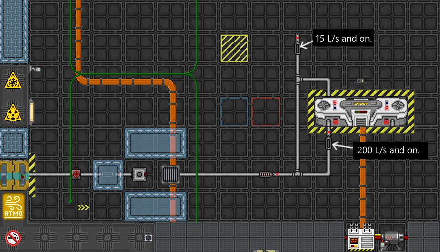
- A secondary key importance to the hot loop is leaking volume from the loop. This is important because it prevents volumetric lockout so it aids in keeping the hot gas flowing in a loop which is what we want.
The Cold-Loop
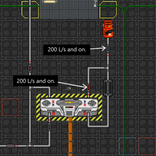
The cold loop is really simple to setup. The logic behind the cold loop is a bit more complicated though. Essentially we want it to be as cold as possible without losing pressure as pressure plays a vital role in energy production. This is why I have found that using a single spaced radiator is both the most time efficient and does not compromise the pressure. It may scare some more experienced atmosians to try this out but I encourage you to try it. Through extensive testing I have found that the cold loop prefers to be between 100C to 400C which typically ends up being ~4k kPa.
- The build is simple here but the most important factor is to use a plasma canister over any other. This is because plasma is more thermo-conductive than other gasses. This leads to usually a gain in 20kw of power just for using plasma canister over other canisters.
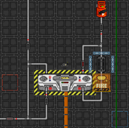
- Now we make a horseshoe shape around the radiator with directional reinforced windows using your RCD. Put a gas trap by placing a holo-projected firelock with your holographic projector.
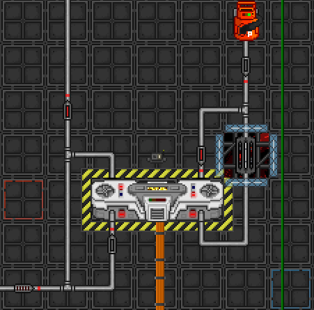
- Space the floor tile below the radiator and then close the box of directional reinforced windows. (Both using your RCD)
Finishing the Hot-Loop
It's time to finish the hot loop now that we have everything else setup.
- Place a holographic firelock on the empty space of the "rectangle" burn chamber we created earlier. Then light a flare or a welder and place it on top of the passive vent. Make sure to turn on the air injector and valve at this point. To do so click on them to make them to have a green indicator on their "light".
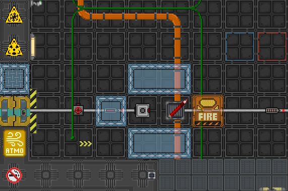
- Make sure that the air injector and the valve are on and the fire is starting to burn. Close the box with another reinforced window where the holographic airlock is.
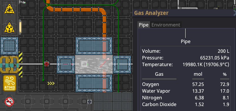
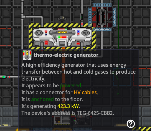
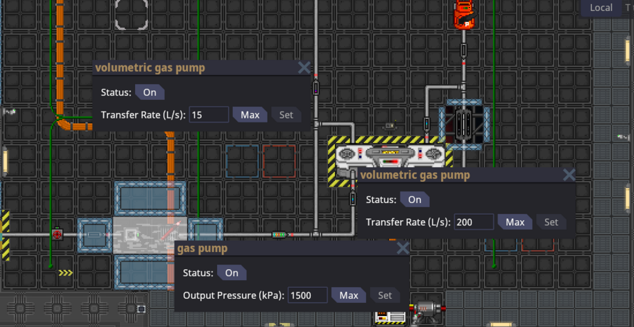
- Use a gas analyzer on the pipe that's coming out of the output of the burn chamber. Wait until it is ~20,000C. Turn on the gas pump at 1500 kPa. This pump controls your power output maximum.
Final thought / Full build
This build is capable of a maximum output of 1.4 MW of power at 4500 kPa of pressure on the gas pump.
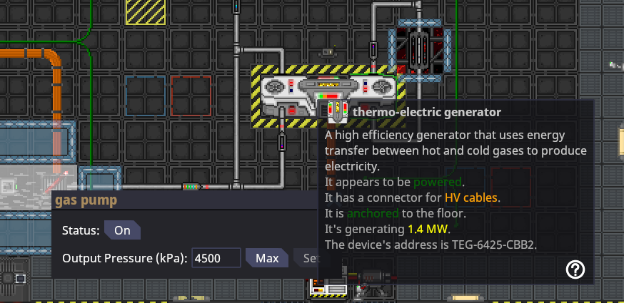
This is the completed TEG image for quick reference.
FAQ
- I followed all the steps but my TEG doesn't produce nearly as much power, why's that?
- What's most likely occurring is that you have multiple power sources on the station active at one time. The way that power is displayed is that it shows its active contribution to the station and not it's theoretical maximum. If you were to turn off all power sources on the station and add more power intensive devices then the TEG would show a higher value. This is also why I have a substation and an emitter below the TEG. I altered the power draw of the emitter to be enormous so that the TEG can show how much power it should be producing at max draw. Power distribution and how it takes priority is a whole another topic to delve into but if you're seeing numbers ranging from 100-200kw then you've built it correctly. You could even turn down the gas pump to accommodate for other power sources. Play with the pressure and get a feel for what it's capable of.
- I messed up the gas chamber really bad how do I fix it?
- Don't worry it's an easy fix with this setup.
- Just turn off the valve inputting into the burn chamber and max out the output of the gas pump coming out of the burn chamber. ## You should also max out the volumetric gas pump coming out of the hot loop that's going into space.
- Check if the burn chamber is empty (use a gas analyzer on the output pipe).
- When the burn chamber is empty fix the problem that broke the burn chamber, turn off the gas pump that's coming out of the output of the burn chamber, and then ignite a new flare/welder on top of the passive vent again.
- Close the burn chamber and then turn on the valve on the input side of the burn chamber, wait for 20,000C and turn on the output gas pump.
- This should empty your burn chamber without any major fixes.
Radioisotope Thermoelectric Generators (RTGs)
Making power using an RTG is similar to making power using solar. RTGs only provide 10 kW[2] of power, but they provide it for free and for the entire round. Basically, if you connect an RTG to your power grid, it'll give you free power. Sometimes, RTGs are damaged. Damaged RTGs[3] behave just like regular ones, but they're radioactive.
Radioactive Radioisotope Thermoelectric Generator (RRTG) Setup
You can use the radioactive nature of the RTG to your advantage. Lord Singuloth generates power by emitting radiation into radiation collectors. Likewise, you can surround an RRTG in radiation collectors and generate as much as ~200-300KW with one RRTG.
Containment-based Engines
Gravitational Singularity Engine
The Gravitational Singularity Engine is one of the most well known and potentially dangerous ways of generating power in Space Station 14. To build it, you need a particle accelerator and singulator generator to spawn a singularity, containment field generators to trap it in a tiny box so it doesn't kill everyone, emitters to power the containment field generators, and radiation collectors to turn the radiation the singularity generates into sweet, sweet power.
If someone turns off the containment field, the singularity will escape and everyone will die. If someone turns the particle accelerator up too much for too long, the singularity will get too big, escape, and then everyone will die. If you get hit by emitter beams, they'll hurt you real bad, and you might die. The singularity engine is super deadly - but damn if it doesn't give the station lots of power.
To keep the singularity from breaking containment, set the particle accelerator to 1. At this setting it will eventually die out. Any more than that and it'll slowly (or quickly) grow until it escapes. Turning it up to higher numbers is OK for short bursts just to kickstart the engine, though - but be careful.
The largest size singularity before you risk it breaking loose can generate between 1.4 and 1.6 MW with 24 radiation collectors. The amount of power the singularity engine generates changes from station to station, because the layout of the engine is different on different stations. One source of the variance is the location of the radiation collectors on each station. Radiation falls off over distance, so on stations where the radiation collectors are further away, you'll get less power.
Radiation collectors require plasma gas to run. If your singularity isn't giving you any power, make sure that your radiation collectors are on and contain tanks full of plasma.
A tell-tale sign of the singularity's proximity is the gravitational lensing effect; the closer you are, the stronger the distortion.
ALL HAIL LORD SINGULOTH
As stated before, the singularity is an incredible powerful resource, equally deadly and beautiful, and in the wrong right hands, an unpredictable tool of chaos: a traitor seeking to force an evacuation, or die a glorious death may find it useful to leave the particle accelerator on the 2 setting or higher in order to swell the singularity past containment. As one might expect, it is typically a good idea to make sure you clear a wide distance from the
DISCLAIMER: It is generally inadvisable to intentionally loose the singularity as a non-antag without good reason. Be prepared to get robusted, lynched and/or banned if you set it loose for shits and giggles.
- ↑ https://github.com/space-wizards/space-station-14/blob/master/Content.Server/Atmos/Reactions/PlasmaFireReaction.cs#L47
- ↑ https://github.com/space-wizards/space-station-14/blob/6e91190478ec03e038ff1c3a10ecd632808f281e/Resources/Prototypes/Entities/Structures/Power/Generation/generators.yml#L239
- ↑ https://github.com/space-wizards/space-station-14/blob/6e91190478ec03e038ff1c3a10ecd632808f281e/Resources/Prototypes/Entities/Structures/Power/Generation/generators.yml#L275-L318
