Power
Power
Engineering generates power, which is essential for keeping a well-functioning space station from descending into darkness. Most computers, machines, lighting fixtures, and more require power to operate.
Supply and Demand
Running an efficient power operation is about delicately balancing the supply of power from generators with demand from station equipment. Thanks to cutting-edge energy storage technology (SMES, and batteries in substations and APCs) aboard NanoTransen stations, generators do not have to always match instantaneous station demand; it is enough to generate enough power to meet the average station demand.
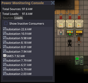
Use the Power Monitoring Console to determine the station's power demand. In a well-functioning station, SMES balance the instantaneous demand with supply. Don't let them run out!
If long term demand exceeds supply, you will have angry station inhabitants complaining about lack of power. When supply exceeds demand, the extra power is used to charge energy storage devices. When all energy storage devices are full, the excess power is safely dissipated into space.
It is better to be in a long-term energy surplus than an energy deficit. On the other hand, if your station is powered by non-renewable sources like the Anti-Matter Engine (AME), generating much more power than you need wastes fuel and contributes to space warming, not to mention, wastes cargo's money which they would have wasted on a lasers crate anyway.
The Power Hierarchy
Power transmission in SS14 comes in three different flavors, high voltage (HV) cables (orange), medium voltage (MV) cables (yellow) and low voltage (LV) cables (green).
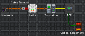
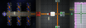
Power flows from generators and power storage via HV cables to substations around the station. From substations, MV cables going out transmit power from the substation and connected grid to area power controllers (APCs) where LV cables take the power the rest of the way to consumers (3-4 tile radius from the APC to devices in the area). A cable must be placed under generators, storage, substations and APCs for them to function.
Separating your Grid
One device not mentioned so far is the cable terminal. In order to separate part of your power network you will need to use a cable terminal, with a HV cable on the terminal box side and the wire side facing towards a SMES. Note the cable terminal will act as a separator for HV cable, if two HV cables are right net to each other and a connecter is placed upon them it will separate those two cables. When a HV cable is then placed under the SMES this creates two distinct HV cable networks; the side with your generation on which ends at the cable terminal, and the storage / supply side which starts at the SMES and goes out to substations.
Currently if you place a substation on the generation side of your SMES it will drain into said SMES as a supplier. This is important as in this scenario if there isn't enough generation, the substation will drain to empty causing a blackout in its connected APCs while everything on the SMES side will remain powered.
Generation
All power on the station comes from either a generator or an energy storage device. In this section we will discuss generators, and in brief, engines. All engines are generators but not all generators are engines.
The Antimatter Engine
The Antimatter Engine (AME) is not always the main source of power for most stations. However, the AME should be your temporary fix in order to keep the station powered until you can get one or more engines up (TEG, Tesla, Singularity, Solars). Engineering is responsible for setting up the AME at round start.
Setup
- Grab AME parts from a Packaged antimatter reactor crate and place one on each floor tile you want a piece of the reactor. The minimum is a 3×3 square, which gives one core.
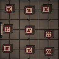
3×3, 1-core AME - With a multitool in hand, click the AME parts on the floor to build a piece of the reactor. If you mess up, you can deconstruct a built reactor with a lit welder.
- Open the antimatter control unit crate to obtain an AME Controller. Place it next to the reactor you just built and wrench it down. The HV cable underneath the controller will carry power produced from the AME. Make sure the controller is on HV wire.
- Open the antimatter containment jar crate to obtain antimatter containment jars. This is the fuel for the AME. With it in hand, click on the controller to place it in the AME. Change the Injection Amount to the desired level (see table below) and click Toggle Injection to turn the AME on.
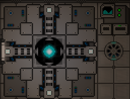
Finished AME
The wattage produced by the AME in different configurations is shown below. The color indicates the state - green: safe, yellow: Overloaded (explodes eventually), Orange: Heavily Overloaded (explodes soon), Red: Extremely Overloaded (explodes within the minute)
| Cores | |||||||||||
|---|---|---|---|---|---|---|---|---|---|---|---|
| 1 | 2 | 3 | 4 | 5 | 6 | 7 | 8 | 9 | 10 | ||
| Injection | 2 | 80.0 | 40.0 | 26.7 | 20.0 | 16.0 | 13.3 | 11.4 | 10.0 | 8.9 | 8.0 |
| 4 | 320.0 | 160.0 | 106.7 | 80.0 | 64.0 | 53.3 | 45.7 | 40.0 | 35.6 | 32.0 | |
| 6 | 720.0 | 360.0 | 240.0 | 180.0 | 144.0 | 120.0 | 102.9 | 90.0 | 80.0 | 72.0 | |
| 8 | 1,280.0 | 640.0 | 426.7 | 320.0 | 256.0 | 213.3 | 182.9 | 160.0 | 142.2 | 128.0 | |
| 10 | 2,000.0 | 1,000.0 | 666.7 | 500.0 | 400.0 | 333.3 | 285.7 | 250.0 | 222.2 | 200.0 | |
| 12 | 2,880.0 | 1,440.0 | 960.0 | 720.0 | 576.0 | 480.0 | 411.4 | 360.0 | 320.0 | 288.0 | |
| 14 | 3,920.0 | 1,960.0 | 1,306.7 | 980.0 | 784.0 | 653.3 | 560.0 | 490.0 | 435.6 | 392.0 | |
| 16 | 5,120.0 | 2,560.0 | 1,706.7 | 1,280.0 | 1,024.0 | 853.3 | 731.4 | 640.0 | 568.9 | 512.0 | |
| 18 | 6,480.0 | 3,240.0 | 2,160.0 | 1,620.0 | 1,296.0 | 1,080.0 | 925.7 | 810.0 | 720.0 | 648.0 | |
| 20 | 8,000.0 | 4,000.0 | 2,666.7 | 2,000.0 | 1,600.0 | 1,333.3 | 1,142.9 | 1,000.0 | 888.9 | 800.0 | |
| 22 | 9,680.0 | 4,840.0 | 3,226.7 | 2,420.0 | 1,936.0 | 1,613.3 | 1,382.9 | 1,210.0 | 1,075.6 | 968.0 | |
Maintenance
The AME will stop generating power when its fuel has been used up. It is wise to periodically check on the AME to make sure it is not out of fuel. If the fuel runs out, you must refuel it:
- Make sure injection is off.
- Eject the existing fuel jar from the AME.
- Place a new fuel jar into the AME.
- Turn the AME back on.
It is also wise to periodically check on the AME, since it is a prime target for sabatoge.
You can see if the AME is currently overloaded (and thus taking damage), if the cores glow in a "+"-shape instead of a ball.
The display of the AME controller indicates if the AME has suffered internal damage. If it is blue, at least 50% of the internal shielding is remaining. If the display shows a red wave, it is below 50%. If the display starts showing swear words, the AME is about to explode.
Solar Power
Solar power is a passive means of generating power. A solar array is made up of a number of solar panels, a single solar tracker device and a solar control computer (console) nearby to properly control and manage the panels.
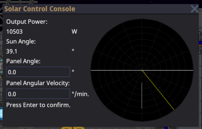
Most if not all solar arrays start off not connected to the station, and need to be connected via HV cables underneath each panel and connected back to the station. Once connected, use the solar control computer to change the angle and speed of tracking for the panels as shown below:
Notice the graph on the right has a T shaped white line and a yellow / golden line. The aim is to alter the panel angle (white T line) to match the sun angle (yellow line). Some experimentation might be needed to setup the angular velocity correctly so that the lines stay in sync and generate maximum wattage. Note: a general start for the angular velocity is somewhere around 5-6 degrees per minute.
A typical panel near max output will produce 1500W (1.5kW). This would be enough to power roughly 1 machine and 1 computer (this figure may change as balance changes are made).
Small Portable Generators
The simplest and most basic of all generators on this list are the "P.A.C.M.A.N." line of portable generators. The J.R.P.A.C.M.A.N. can be found in maintenance areas, and runs on simple welding fuel, also found in maintenance. Anchor it to an LV cable and power it up. Because it generates LV power, it is only able to power one APC's worth of devices. It also generates exhaust fumes, so make sure you set it up in a well-ventilated area.
The other "P.A.C.M.A.N." generators are intended for usage by engineering for advanced power scenarios. Bootstrapping the engine, powering departments, and so on. unlike the J.R.P.A.C.M.A.N., They connect directly to MV or HV power cables, and are able to switch between them for flexibility. the standard P.A.C.M.A.N. is powered by solid plasma, and the S.U.P.E.R.P.A.C.M.A.N. runs on uranium, and produces enough power for things like shuttles.
Gravitational Singularity Engine
The Gravitational Singularity Engine is one of the most well known and potentially dangerous ways of generating power in Space Station 14. To build it, you need a particle accelerator and singulator generator to spawn a singularity, containment field generators to trap it in a tiny box so it doesn't kill everyone, emitters to power the containment field generators, and radiation collectors to turn the radiation the singularity generates into sweet, sweet power.
If someone turns off the containment field, the singularity will escape and everyone will die. If someone turns the particle accelerator up too much for too long, the singularity will get too big, escape, and then everyone will die. If you get hit by emitter beams, they'll hurt you real bad, and you might die. The singularity engine is super deadly - but damn if it doesn't give the station lots of power.
To keep the singularity at a constant size, turn your particle accelerator to 2. Any more than that and it'll slowly (or quickly) grow until it escapes. Turning it up to higher numbers is OK for short bursts just to kickstart the engine, though - but be careful.
The largest size singularity before you risk it breaking loose can generate between 1.4 and 1.6 MW with 24 radiation collectors. The amount of power the singularity engine generates changes from station to station, because the layout of the engine is different on different stations. One source of the variance is the location of the radiation collectors on each station. Radiation falls off over distance, so on stations where the radiation collectors are further away, you'll get less power.
Radiation collectors require plasma gas to run. If your singularity isn't giving you any power, make sure that your radiation collectors are on and contain tanks full of plasma.
The Thermoelectric Generator (TEG)
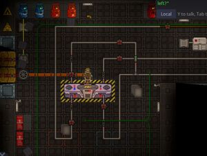
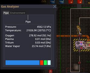
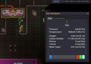
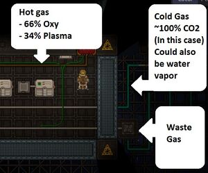
The TEG involves atmospherics, so you should have a decent understanding of atmos before setting it up by yourself. As evidence of this point, there are several ways to set up the TEG. As this section is filled out, there may be several guides posted on different ways to configure the TEG. However, there is one key insight that you should keep in mind which establishes the law that defines how each system is designed. That is, the TEG is powered by a temperature exchange between hot and cold gasses. As such, one side should be very hot, and the other should be (relative to the other side) quite cold. Every configuration of TEG will result in this kind of configuration.
Infinite Power Configuration (IPC)
This configuration will allow the station to generate infinite power for the duration of the round. As with any piping system, you will have your inputs and outputs. That is, where does the gas come from, and where does it go? For the infinite configuration, generally speaking, there are two inputs and one output.
Inputs
- Gas A source
- Gas B source
Generally gases A and B are different, but they may not need to be.
Output
- Space
That is to say, for IPC you will need to build pipes from two gas miner sources, pipe them through the generator, and then combine both of them into one pipe that will go out to space to release the waste gas. Refer to the examples below.
Oh, also don't forget to add a heater to the start of the hot gas.
Single Mine Configuration (WIP)
Inputs
- Gas A (oxy/plasma mix)
Output
- Space Vent (mostly unused)
Details: make circle on left and right side of teg. One with space radiator(cold), the other with contained radiator(hot). Fill cold side with gas, fill hot side with gas. Start pumping both. Expose hot radiator to source vent with oxy/plasma mix (34/66 ratio). Burn until it gets super hot. Turn of supply valve when done. Will generate power until too cold. When too cold, dump hot gas into space vent on hot side, repeat process.
Radioisotope Thermoelectric Generators (RTGs)
Making power using an RTG is similar to making power using solar. RTGs only provide 10 kW of power, but they provide it for free and for the entire round. Basically, if you connect an RTG to your power grid, it'll give you free power.
Sometimes, RTGs are damaged. Damaged RTGs behave just like regular ones, but they're radioactive. That means they're more dangerous, but on the bright side, you can put radiation collectors next to them to turn that radiation into more power.

